Key features
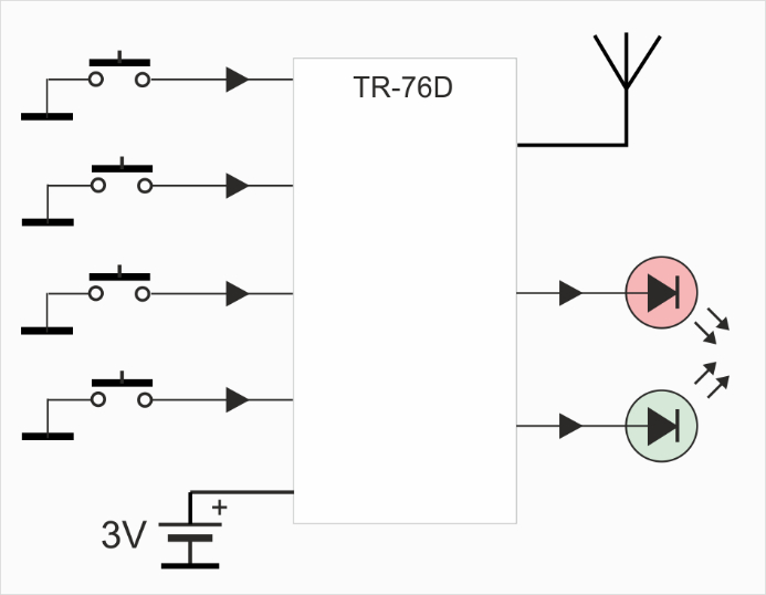
- IQRF transceiver TR-76D inside
- Bidirectional RF communication providing high security in comparison
- to unidirectional systems
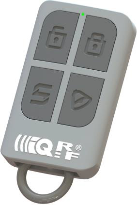
- 4 pushbuttons
- 2 LEDs (visible through one peephole)
- Ultra low power consumption
- Coin battery CR2032
- Programmable via RF (wireless upload). For development and service, also wired upload is possible.
Applications
- Remote controller for arbitrary use
- Internet of Things
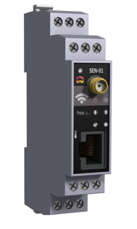
| RF transceiver |
TR-76D |
| Antenna |
Shortened λ/4 whip built in the RC4-02 PCB board |
| RF band |
868 MHz or 916 MHz, multiple channels, SW selectable |
| Effective radiated power |
Programmable in 8 levels up to the following values: |
| - 868 MHz band |
-10 dBm |
| - 916 MHz band |
-9.4 dBm (channel 255) |
| RF range |
Up to 165 m |
| Battery |
CR2032, 3 V, 210 mAh, lithium coin cell 20 mm x 3.2 mm |
| Supply current |
|
| - TR in Deep sleep mode |
100 nA (all TR peripherals inactive, LEDs off, pushbuttons not pressed) |
| - TR in Sleep mode |
700 nA (all TR peripherals inactive, LEDs off, pushbuttons not pressed) |
| Operating temperature |
-10 °C to +50 °C |
| Size |
59 mm x 36 mm x 12 mm |
| Weight |
17 g |
Power supply
RC4-02 is supplied from the 3 V, 210 mAh lithium non-rechargeable coin 20 mm x 3.2 mm battery CR2032. It is possible to use even a battery with a slightly higher capacity, e.g. 230 mAh (depending on the vendor). Exchanging is possible after unscrewing the rear cover. The polarity must correspond to the silkscreen marking at the bottom PCB side. RC4-02 is protected against the damage due to the wrong polarity.
The power supply can not be switched off at all (unless removing the battery), the TR sleep mode should be used instead of this. See chapter Sleep mode below.
TR transceiver
The TR-76D transceiver is used.
Because the TR is soldered (non-removable), the recommended way to upload the application code into TR is wireless upload (RFPGM). Thus, the application engineer should keep a method how to enter RFPGM during development. See chapter Demo application for details.
However, it is also possible to use wired upload. In this case, the TR upload interface (with soldering pads only, 2.54 mm pitch) is intended to connect the CK-USB-04A programmer by wires. Refer to the CK-USB-04A User's guide, chapter Incircuit upload.
Antenna
The antenna is built in the RC4-02 PCB board.
Pushbuttons
The functionality of all four pushbuttons S1 to S4 is fully under control of the application software.
All pushbuttons are active at a log. high level. To provide a log. low level in the inactive state, the pushbutton pins have on-board pull-down resistors.
The pushbuttons have no hardware protection against contact bouncing when pressed and released. The protection should be ensured in software.
LEDs
Green LED and red LED are connected to TR pins dedicated to IQRF OS and DPA indication. Additionally, during normal
operation, the functionality of both LEDs is under the control of application software. They are active at the log. high level. Both LEDs are visible through one peephole.

 Datasheet